Drone Assembly - SolidWorks Design
Aafreen KaurProject Overview
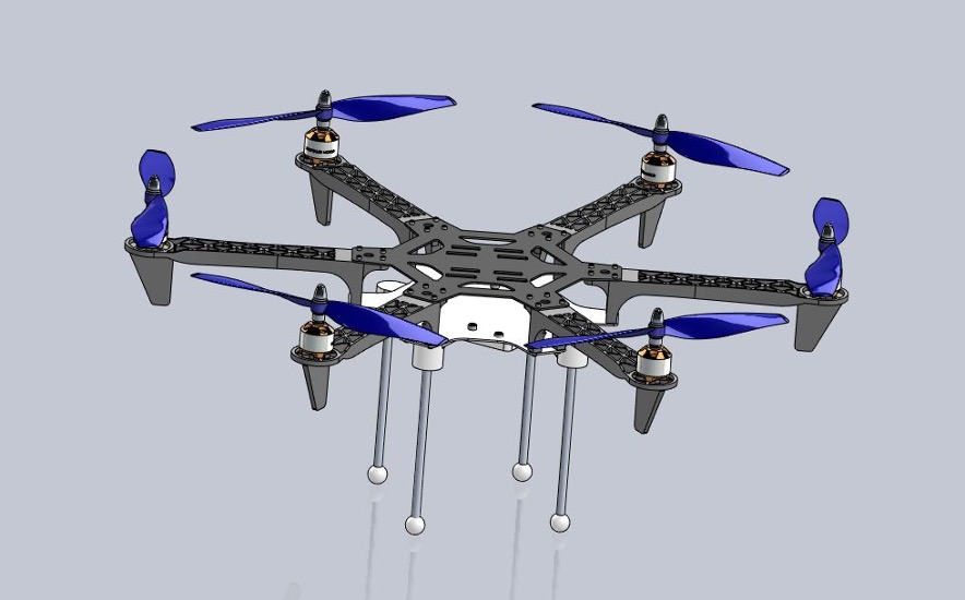
This project involves designing a modular drone system using SolidWorks, aimed to create a robust and efficient design process, modular assembly, and comprehensive documentation.
Design Components
The design includes two sub-assemblies:
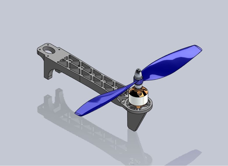
- Propeller Arm Assembly: Comprising propeller blades, motor mounts, and supporting structures.
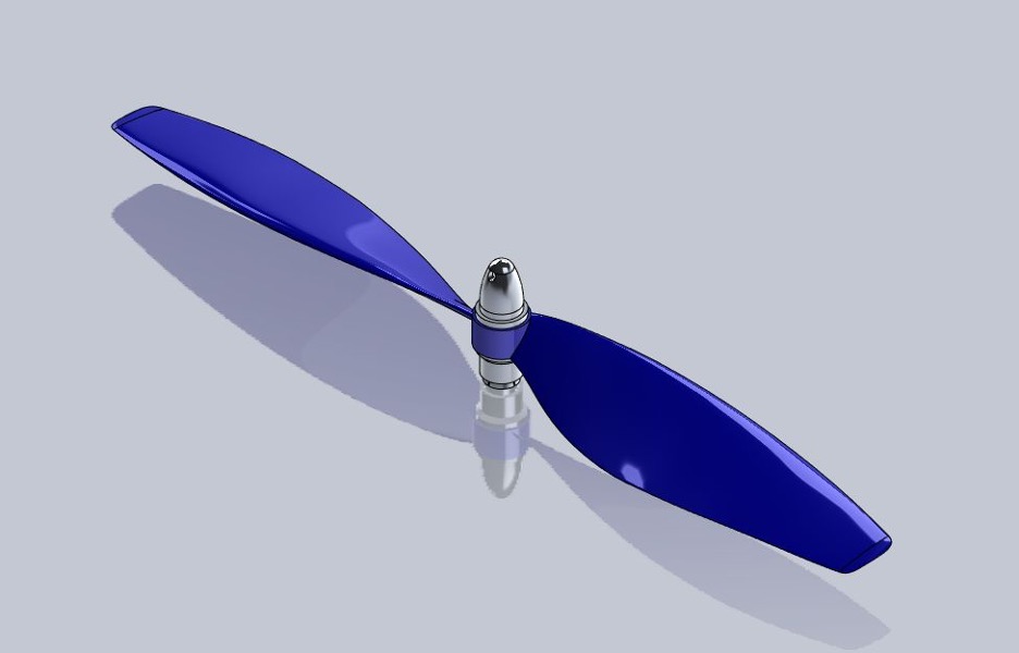
- Propeller Assembly: Including the propeller itself, hub, and fastening screws.
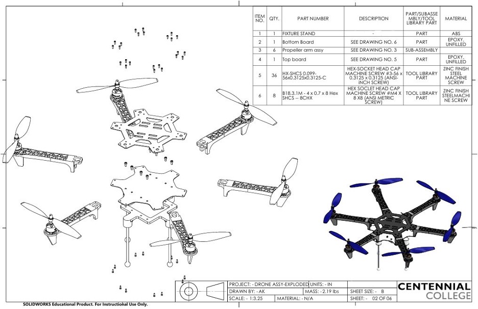
List of Components
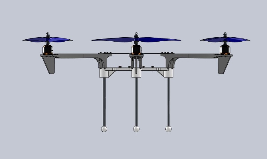
- Fixture Stand: Acts as the support base for the entire drone.
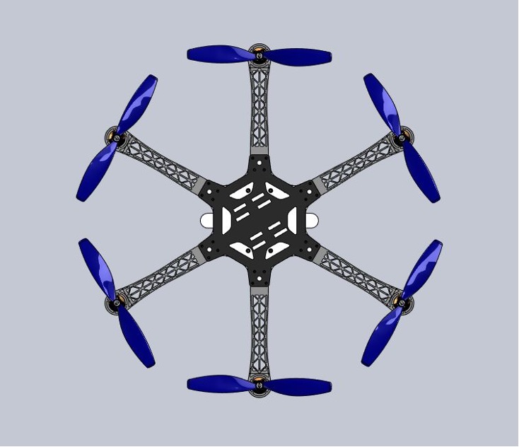
- Bottom Board: Provides structural integrity and houses internal components.
- Top Board: Covers and protects internal circuitry.
- Propeller Arm Assembly: Sub-assembly comprising motor mount, support structure, and fasteners.
- Hex-Socket Head Cap Machine Screws:
- Size: #3-56x0.3125x0.3125 (ANSI Inch Screw). Used for critical components like motors.
- Size: M4x8 (ANSI Metric Screw). Used for minor components fastening.
Workflow
-
Individual Part Modeling: Each component was meticulously designed with exact dimensions and tolerances.
-
Sub-Assembly Creation: Smaller assemblies like the propeller and arm were created and tested for fit and function.
-
Final Assembly: All parts were integrated into a cohesive design using SolidWorks assembly constraints.
-
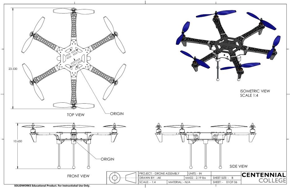
Documentation: A comprehensive drawing set was prepared, including views, dimensions, and BOM.